 +90 282 676 48 90


- CORPORATE
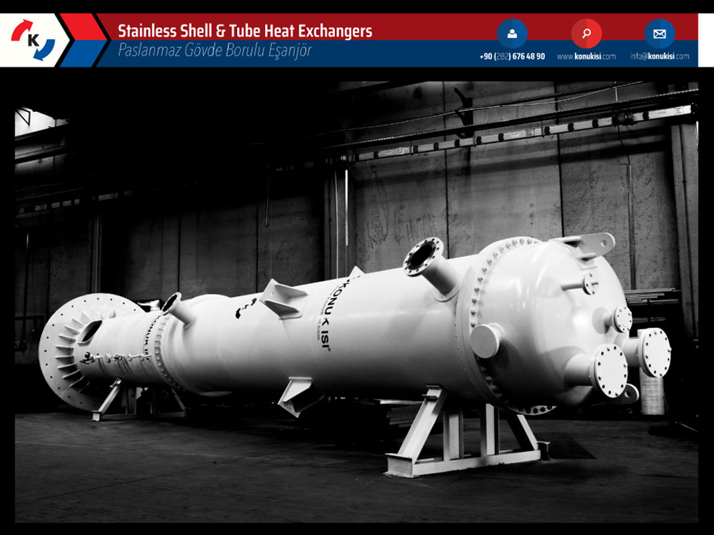
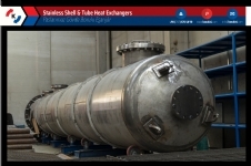
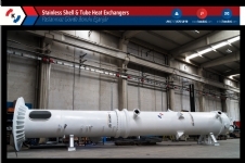
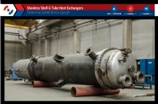
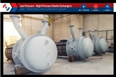
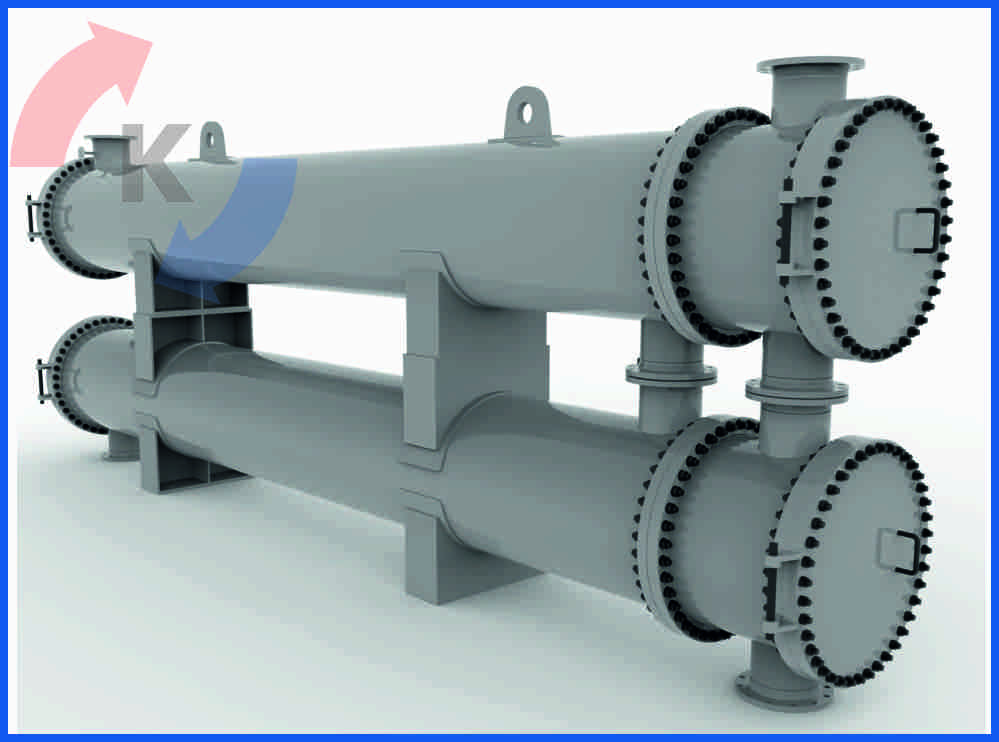
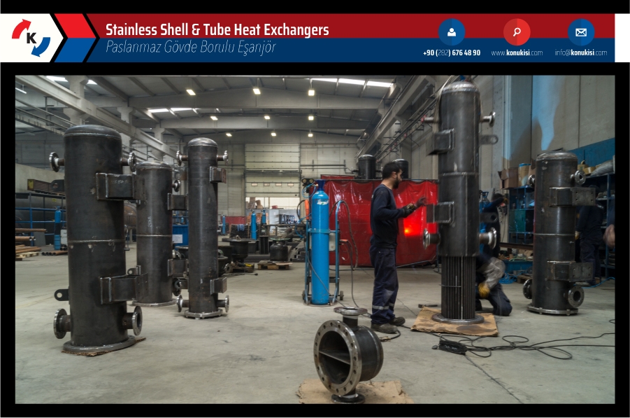
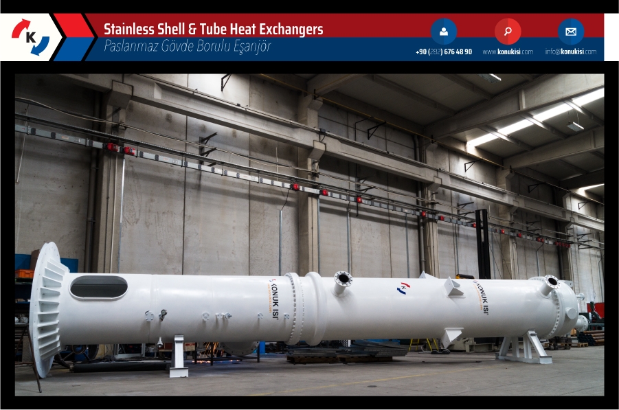
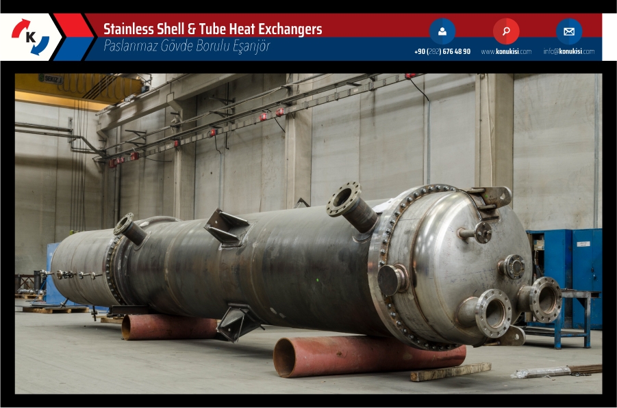
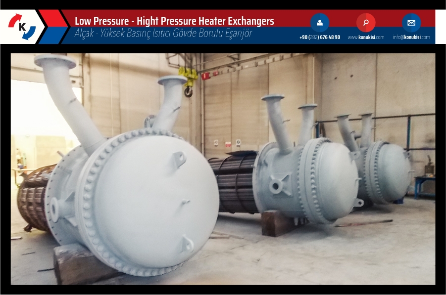
Shell & Tube Heat Exchangers

 Heat exchanger technical data:
Technical parameters and important details:
- Weight up to 100 tonnes
- Length up to 25 m
- Minimum tube diameter 12 mm
Materials:
- Carbon Steel, Stainless Steel, Duplex Steel, Special Alloys (mostly 825 and 625), Copper, Brass, Titanium
Casing & Tube Heat Exchangers designed to standards:
- TEMA RCB, HEI, HTRI / HTFS Thermal calculation, API 660, Special design, On request, CFD possible
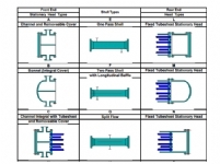
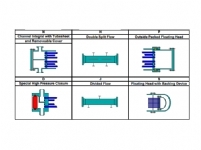
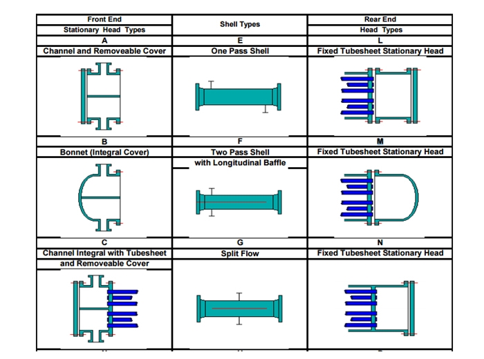
The Tubular Heat Exchanger Manufacturers Association (TEMA) standards describe in detail the components of shell and tube heat exchangers. Shell and Tube heat exchangers consist of three parts. Front head, body and rear head. According to the TEMA standards, heat exchangers are illustrated as follows:
 Catalogue
What is a heat exchanger ?
Catalogue
What is a heat exchanger ?
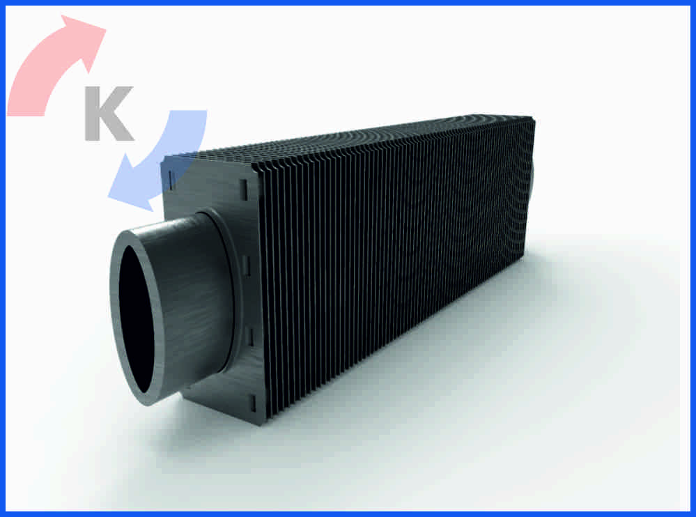
A heat exchanger is a device used to transfer heat between a solid object and a fluid, or between two or more fluids. The fluids may be separated by a solid wall to prevent mixing or they may be in direct contact. They are widely used in space heating, refrigeration, air conditioning, power stations, chemical plants, petrochemical plants, petroleum refineries, natural-gas processing, and sewage treatment. The classic example of a heat exchanger is found in an internal combustion engine in which a circulating fluid known as engine coolant flows through radiator coils and air flows past the coils, which cools the coolant and heats the incoming air. Another example is the heat sink, which is a passive heat exchanger that transfers the heat generated by an electronic or a mechanical device to a fluid medium, often air or a liquid coolant.
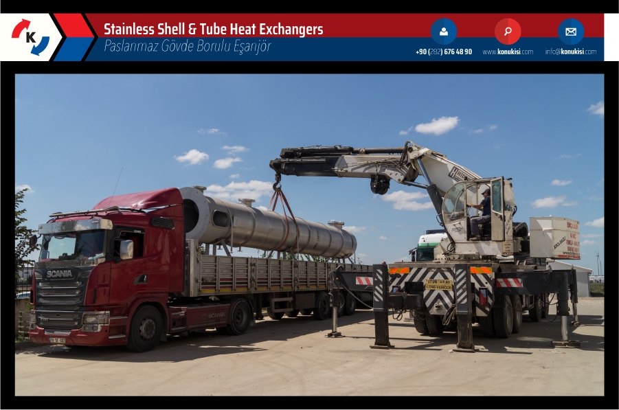
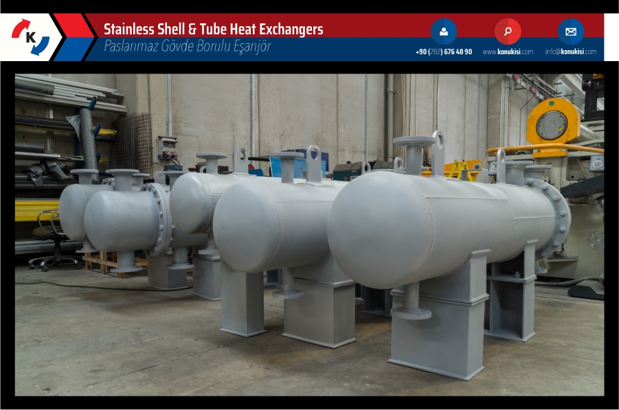
Shell & tube heat exchangers are manufactured according to a design project specially prepared by KONUK ISI with considering the project received from any customer as a basis and with also considering their needs.
With a compensator used in the exchanger shell, the expansions due to temperature differences and material properties during the heat transfer are thus absorbed and as a result the life expectancy of the exchanger is increased.
In shell & tube heat exchanger manufacturing carbon steel, stainless steel, copper and tubes with special alloys (bafon, brass, etc.) are used.
All our products is manufactured in accordance to international standards as API 660/ ASME VIII Div 1/ TEMA/ AD2000/ CODAP/ PED 97-23.
Technical parameters and important details:
» Weight up to 100 tons
» Length up to 25m
» Minimum tube diameter 12 mm
Materials:
» Carbon Steel, Stainless Steel, Duplex Steel, Special Alloys (mainly 825 and 625), Copper, Brass, Titanium
Design of Shell & Tube Heat Exchangers according to Standards:
» TEMA RCB, HEI, HTRI/HTFS thermal calculation, API 660, Special design, Upon request, CFD possible
The Standards of the Tubular Exchanger Manufacturers Association (TEMA) describe these various components in detail. An STHE is divided into three parts: the front head, the shell, and the rear head.
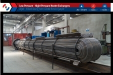
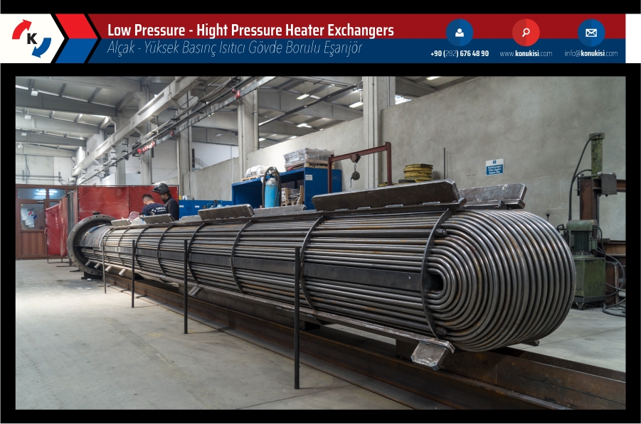
 Tubing may be seamless or welded. Seamless tubing is produced in an extrusion process; welded tubing is produced by rolling a strip into a cylinder and welding the seam. Welded tubing is usually more economical.
Normal tube diameters are 5/8 inch, 3/4 inch and 1 inch. Tubes of smaller diameter can be used but they are more difficult to clean mechanically. Tubes of larger diameter are sometimes used either to facilitate mechanical cleaning or to achieve lower pressure drop.
The normal tube wall thickness ranges from 12 to 16 BWG (from 0.109 inches to 0.065 inches thick). Tubes with thinner walls (18 to 20 BWG) are used when the tubing material is relatively expensive such as titanium.
Tubesheets are plates or forgings drilled to provide holes through which tubes are inserted. Tubes are appropriately secured to the tubesheet so that the fluid on the shell side is prevented from mixing with the fluid on the tube side. Holes are drilled in the tubesheet normally in either of two patterns, triangular or square.
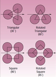
Tube pitch is defined as the shortest distance between two adjacent tubes. For a triangular pattern, TEMA specifies a minimum tube pitch of 1.25 times the tube O.D. Thus, a 25- mm tube pitch is usually employed for 20-mm O.D. tubes. For square patterns, TEMA additionally recommends a minimum cleaning lane of 4 in. (or 6 mm) between adjacent tubes. Thus, the minimum tube pitch for square patterns is either 1.25 times the tube O.D. or the tube O.D. plus 6 mm, whichever is larger. For example, 20-mm tubes should be laid on a 26-mm (20 mm + 6 mm) square pitch, but 25-mm tubes should be laid on a 31.25-mm (25 mm*1.25) square pitch.
Baffles serve three functions:
1) Support the tube
2) Maintain the tube spacing
3) Direct the flow of fluid in the desired pattern through the shell side.
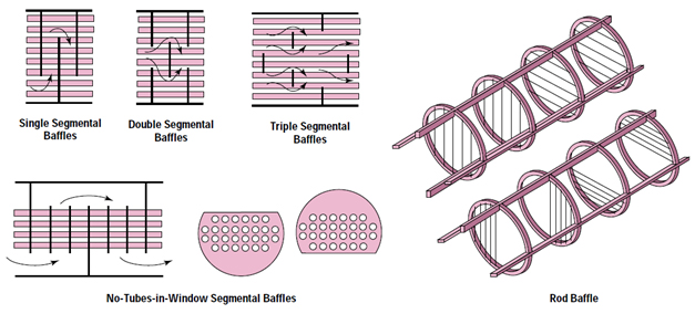
Baffle spacing is the centerline-to-centerline distance between adjacent baffles. It is the most vital parameter in STHE design.
The TEMA standards specify the minimum baffle spacing as one-fifth of the shell inside diameter or 2 in., whichever is greater. Closer spacing will result in poor bundle penetration by the shellside fluid and difficulty in mechanically cleaning the outsides of the tubes. Furthermore, a low baffle spacing results in a poor stream distribution as will be explained later.
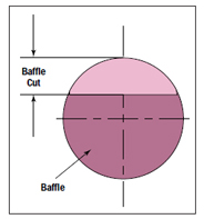
As shown in Figure , baffle cut is the height of the segment that is cut in each baffle to permit the shellside fluid to flow across the baffle. This is expressed as a percentage of the shell inside diameter. Although this, too, is an important parameter for STHE design, its effect is less profound than that of baffle spacing. Baffle cut can vary between 15% and 45% of the shell inside diameter.
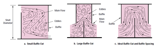
Baffle cuts larger or smaller than the optimum typically result in poorly distributed shell side flow with large eddies, dead zones behind the baffles and pressure drops higher than expected.
Tie rods and spacers are used for two reasons:
1) hold the baffle assembly together; and
2) maintain the selected baffle spacing.
The tie rods are secured at one end to the tubesheet and at the other end to the last baffle. They hold the baffle assembly together. The spacers are placed over the tie rods between each baffle to maintain the selected baffle pitch. The minimum number of tie rod and spacers depends on the diameter of the shell and the size of the tie rod and spacers.
Channels or heads are required for shell-and-tube heat exchangers to contain the tube side fluid and to provide the desired flow path.
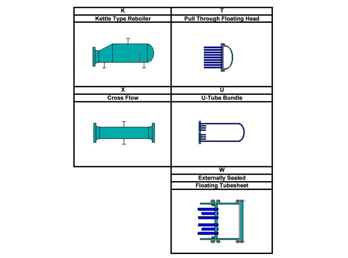
Many types of channels are available. The three (3) letters TEMA designation is the standard method for identifying the type of channels and the type of shell of shell-and-tube heat exchangers. The first letter of the TEMA designation represents the front channel type (where the tube side fluid enters the heat exchanger), the second letter represents the shell type and the last letter represents the rear channel type. The TEMA channel types are shown below.
The channel type is selected based on the application. Most channels can be removed for access to the tubes. The most commonly used channel type is the bonnet. It is used for services which do not require frequent removal of the channel for inspection or cleaning. The removable cover channel can be either flanged or welded to the tubesheet. Flanges are usually not provided for units with larger shell diameters. The removable cover permits access to the channel and tubes for inspection or cleaning without the need to remove the tube side piping. Removable cover channels are provided when frequent access is required.
The rear channel is often selected to match the front channel. For example a heat exchanger with a bonnet at the front head (B channel) will often have a bonnet at the rear head (M channel) and will be designated as BEM. However, there can be circumstances where they are different such as when removable bundles are used.
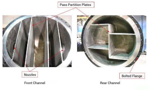
Pass partitions are required in channels of heat exchangers with multiple tube passes. The pass partition plates direct the tube side fluid through multiple passes. The number of tube side passes is normally less than eight, although more than eight passes can in some cases be required. Multiple tube passes allow to maximize the tube side heat transfer within the pressure drop constraint. Typically, heat exchangers with liquid as the tube side fluid have multiple tube passes. Most heat exchangers with large tube side volumetric gas flow rates have a single tube pass.
-
 Shell & Tube Heat Exchanger
CONTACT US Velimeşe Mah. Sultan Sok. No:1 Ergene / Tekirdağ
 +90 282 676 48 90
 +90 533 928 18 25
 +90 282 676 48 98
 info@konukisi.comKonuk Isı Mak. San. ve Tic. Ltd. Şti. © 2023 Tüm Hakları Saklıdır.


 BACK TO TOP